


In real-world data collection (such as laser scanning or drone photogrammetry), raw point clouds are unstructured, lack topological relationships, and contain numerous discrete noise points (referred to as "unstructured point clouds"). Drafting directly while navigating through a massive cloud of points is like searching for wall corners in a fog. Introducing a "reference horizontal plane" for slicing and extraction offers exceptional practical value for surveying and mapping engineering.
1. Eliminating "Roof and Eaves Occlusion" to Reveal True Walls and Corner Points
• Pain Point: When viewing a building from top-down (such as an orthographic view), roofs and overhanging eaves obstruct the true walls underneath.
• Practical Value: By setting a reference horizontal plane at a specific height above the ground (e.g., H = 1.2m) and making a cut, the ceiling and roof are bypassed, retaining only the point clouds near the slice plane. This directly exposes the physical horizontal boundaries of all load-bearing walls, partition walls, columns, and door/window openings, allowing surveyors to accurately capture true "corner points" and completely solving the challenge where eaves obstruction prevents precise measurement of wall bases.
2. Rapid "Data Dieting" to Eliminate CAD/BIM Software Lag
• Pain Point: A complete point cloud of a single building often contains tens to hundreds of millions of points, with file sizes ranging from several gigabytes to tens of gigabytes. Dragging them directly into AutoCAD or Revit causes severe lagging or even software crashes.
• Practical Value: Extracting a slice point cloud of a specific thickness along the reference horizontal plane (or further fitting it into section lines) instantly slashes the data volume by 90% to 95% or more. Surveyors can quickly complete as-built CAD drawings in an ultra-smooth environment, significantly boosting overall office-to-field production efficiency.
3. Achieving High-Precision Assessments of "Levelness and Structural Deformation"
• Pain Point: Building walls may experience tilting, bulging, or differential settlement during long-term use or construction.
• Practical Value:
1) Verticality Analysis: Extracting cross-sections at reference horizontal planes at different elevations (e.g., H = 0.5m, H = 2.5m) and overlaying or comparing these two section contours intuitively measures the tilt amount and tilt direction of the wall in the vertical dimension.
2) Flatness and Bulge Detection: Comparing the extracted cross-section point clouds against standard fitted lines/rectangles enables millisecond-level detection of whether the wall surface has local depressions or bulges (over-thickness or under-thickness).
4. Establishing a Unified Elevation Datum to Standardize Indoor Mapping
• Practical Value: In complex indoor mapping involving multiple rooms and floors, a "reference horizontal plane" provides a unified elevation datum. Extracting sections based on this plane ensures that all room wall thicknesses, door/window opening heights, and indoor area calculations are grounded in the same horizontal reference system, preventing cumulative errors and elevation confusion caused by uneven floors (such as ramps or steps) during manual measurements.
5. Automated "Vector Line Fitting" and Precision Area Calculation
Practical Value:
1)Automated Fitting: Discrete unstructured point clouds cannot be used to calculate area directly. After slicing out point clouds along the reference horizontal plane, computer algorithms (such as RANSAC or Hough transforms) can easily and automatically fit this thin "band of points" into closed 2D vector polylines.
2)As-Built Area Verification: Based on this closed vector contour, engineers can instantly calculate highly accurate interior floor areas, usable areas, and wall footprints, providing legally recognized data support for building completion acceptance, cadastral surveying, and property registration.
Summary
For surveying workflows, extracting building cross-sections from unstructured point clouds via reference horizontal planes serves as the crucial bridge—"precisely distilling centimeter- or even millimeter-level engineering drawings from a chaotic, disordered sea of 3D point clouds." It transforms unusable raw scan data into a standardized engineering language ready for drafting, calculation, and quality acceptance.
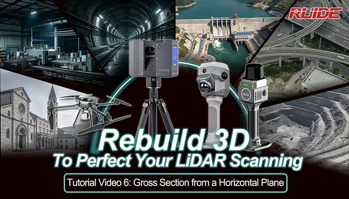
The Rebuild3D plugin built into AcuteLAS Studio 2026 allows users to extract building cross-sections with various custom settings, ensuring high efficiency and precision. Check out the video below for step-by-step instructions.
videos :https://youtu.be/o6dbcvmHYck?si=MA7iWJ3pRRZTsLdv



